

DXC is a twin-platform drone module built around two airframe configurations: X and Deadcat.
Rather than being developed as two separate drones, both configurations are based on a shared core structure. By adjusting selected structural components, the same platform can be configured into either airframe layout. The two versions share the primary frame plates and electronic mounting architecture, while retaining their own arm geometry and platform characteristics.
After more than a month of component fabrication and physical assembly, DXC is no longer just a structural concept in CAD. The first full-scale prototype has now entered actual assembly, allowing us to begin answering questions that could not be fully verified during the design stage: Can all electronic components truly fit within the available space? Will sufficient clearance remain after soldering and wiring are completed? And when the platform is reconfigured into a different layout, can the rear structure still be extended as intended?
The answers to these questions are gradually shaping the design direction of DXC Version 2.
One Shared Core Structure, Two Platform Configurations
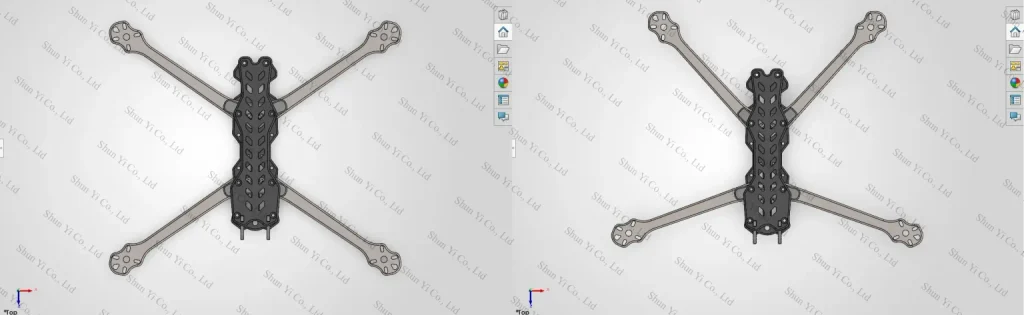
DXC is a twin-platform system developed around a shared core structure, supporting both X and Deadcat airframe configurations.

The two configurations share the primary structural plates and mounting architecture, while selected structural components are adjusted to change the arm layout and overall platform geometry. Rather than forcing two different airframe concepts into a single shape, the design aims to maximize component commonality while preserving the distinct characteristics of each configuration.

For DXC, the X and Deadcat layouts are not two unrelated airframes, but two configurations derived from the same core platform. Verifying this concept is also one of the primary objectives of the first physical prototype.
The Physical Prototype Makes Internal Space Real
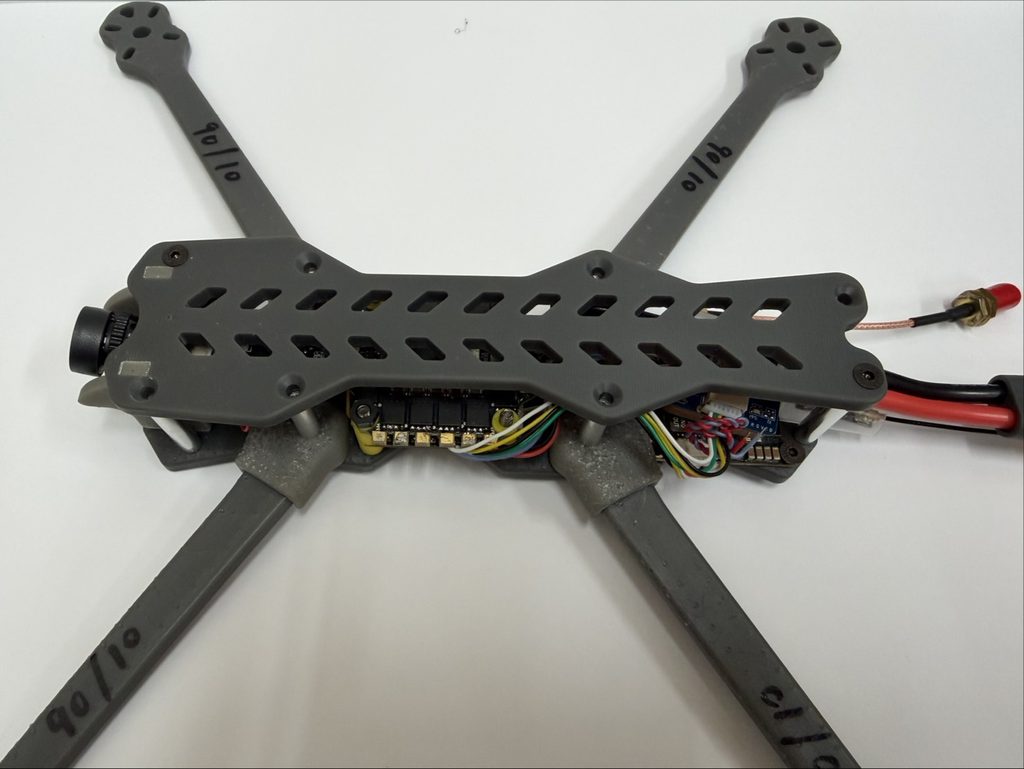
Version 1.2
The first DXC prototype was primarily built to verify the overall airframe proportions, component integration, and the actual placement of electronic systems.

At this stage, the front camera mounting area for a 19 × 19 mm camera, the central electronics stack for the ESC and FC, the top-mounted battery platform, the rear electronics section for the VTX, GPS, and ELRS receiver, as well as the motor-to-arm connection points, have all been physically assembled and tested.

In the CAD model, these compartments already appeared to provide sufficient theoretical space for their intended components. However, only after the parts were installed in the actual frame could we properly evaluate the spacing between components, the real assembly sequence, cable-routing paths, and the clearance required for both assembly and maintenance.

This physical build confirmed that DXC’s main internal layout is workable. It also means that future design revisions will no longer rely solely on component dimensions, but on actual assembly conditions and practical integration requirements.
CAD Can Validate Component Fit, but Not the Full Wiring Layout
The external dimensions of electronic modules can be modeled accurately in CAD, but a real electronic system consists of more than the modules themselves.

Once the 4-in-1 ESC is fully assembled with its power leads and capacitor soldered in place, additional space is required for solder joint height, wire thickness, cable routing and bend radius, capacitor leads, and the chosen method of securing the components. In particular, thicker power cables cannot be bent sharply at arbitrary points, which means that clearances that appear sufficient in CAD may no longer be usable once the system is physically assembled.
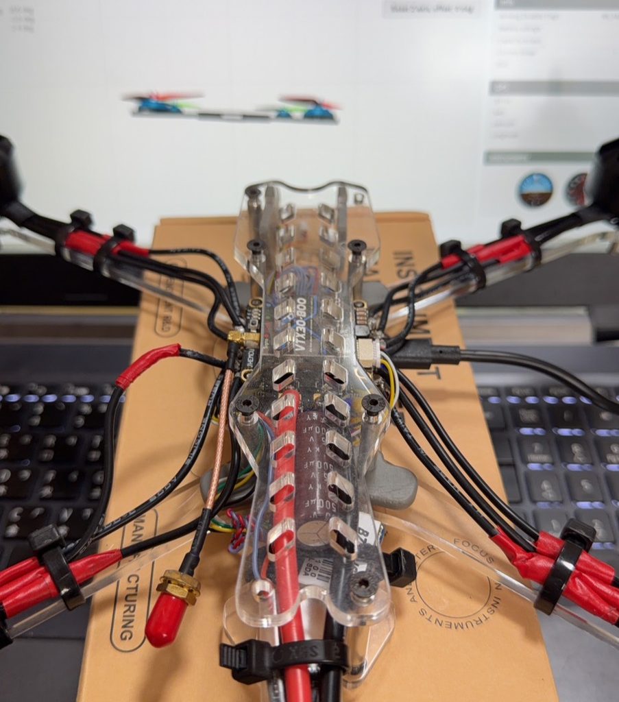
Version 1.1
During the first physical assembly, the central electronics bay was still able to accommodate a 35 V, 1500 μF elongated capacitor after the 4-in-1 ESC had been connected to its power leads and capacitor wiring. This confirmed that the original compartment was not only large enough in theory, but also capable of absorbing the additional space required by real soldering and cable routing.

More importantly, the assembly process helped us identify practical positions for cable routing and capacitor mounting, providing a more realistic basis for defining wiring paths and component placement in future versions.
Rear Extension Limits Defined by Both Configurations
Once the central electronics bay had been verified, the next issue was the available space at the rear of the platform.

Extending the tail section can provide additional mounting space for electronic components, but DXC is not limited to a single airframe configuration. When the platform is reconfigured from X to Deadcat, the positions of the rear arms and propellers change as well. For this reason, the allowable rear extension cannot be determined based on only one configuration.

By physically adjusting DXC between its X and Deadcat layouts, we compared the rear arm positions, propeller disc areas, and the space available for tail extension in both configurations. The results showed that the extended rear structure remained outside the propeller rotation envelope in both layouts and did not interfere with the required propeller clearance.

This result allows DXC to increase the usable mounting space for rear electronic components while preserving its twin-platform reconfiguration capability. It also provides a direct basis for redesigning the rear structure in Version 2.
From Space Optimization to Structural Validation
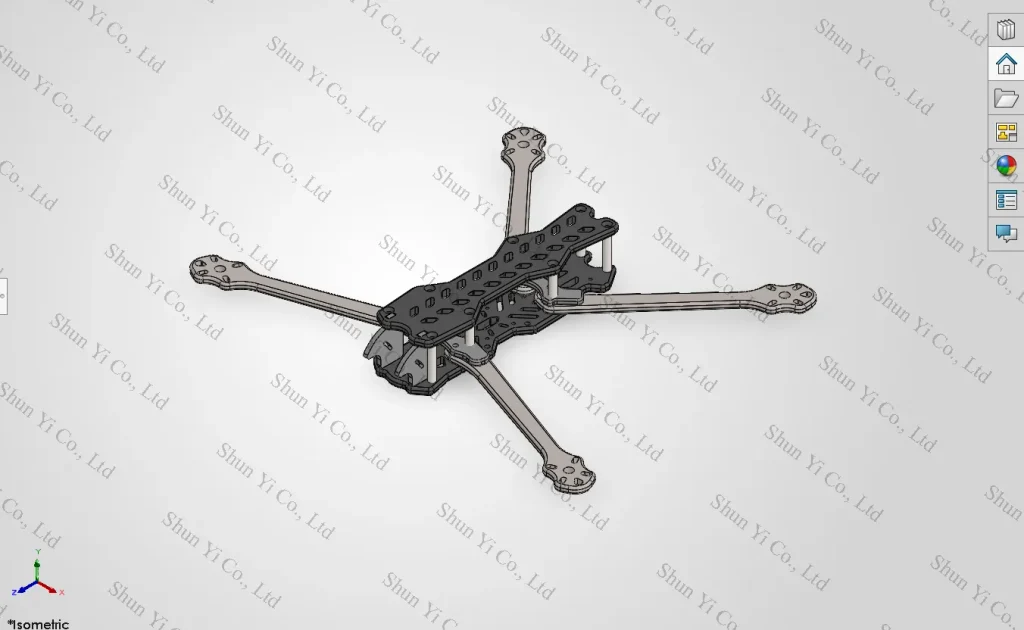
The purpose of Prototype V1.1 was not to directly become the final product, but to subject the overall proportions, core structure, electronics compartments, and twin-platform architecture to physical verification.

The assembly results showed that DXC’s primary design direction is viable. However, once the complete electronic system and wiring are installed, there is still value in reallocating the rear internal space. Since both platform configurations have already been confirmed to provide a safe range for rear extension, Version 2 does not require a complete redesign of the existing structure. Instead, it can build directly on the findings from the first physical test and focus on targeted structural refinements.
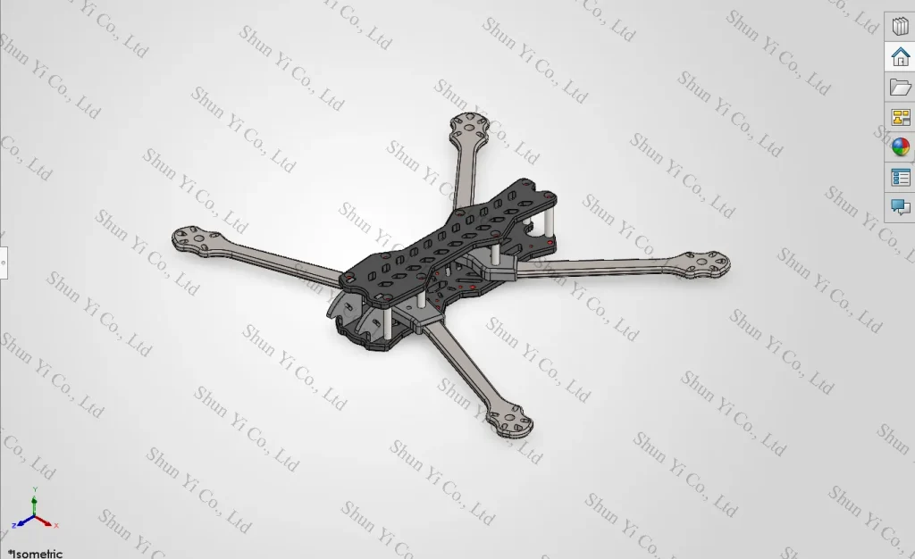
Version 1.2 will extend the rear structure to provide additional usable space for electronic components and will introduce a standard 30.5 × 30.5 mm mounting pattern, allowing the rear compartment to support a wider range of commonly used electronic modules.

In addition to reallocating the available electronics space, the original arm bracket has also been redesigned as a wraparound structure. The revised bracket will enclose both arms simultaneously, creating a more integrated connection between the arms and the core platform while providing a new basis for evaluating fastening methods, load response, and overall structural stability.

From V1.1 to V1.2, the changes to DXC go beyond simply extending the rear section. The development is beginning to move from asking whether individual components can physically fit to whether the electronic system can be integrated in a practical way, and whether the structure can remain stable under real operating conditions.
Next Stage: Physical Validation of the Structure
As the Version 2 structure has taken shape, DXC’s validation focus has gradually shifted from electronics compartments and assembly space toward the structure itself. Evaluation has now begun on the load response and bending deformation of the arms, brackets, and connection areas around the core platform, while different wraparound lengths and structural configurations are being compared to determine their effect on displacement. These results will serve as a design screening basis before the Version 2 prototype is physically manufactured.

The next stage will bring the simulation results into the physical prototype, where arm deflection, vibration, fastening-point stability, and structural performance after repeated assembly will be further evaluated.

CAD established DXC’s first form. The first physical build revealed assembly issues that could not be fully seen on the screen. Version 2 now begins to address a more direct question: not simply whether this twin-platform system can be assembled, but whether it can operate reliably and remain structurally stable under real conditions.
CAD gave DXC its first physical form, while real-world assembly revealed issues that could not be seen in the design alone. The next stage of physical testing will determine how far this twin-platform concept can ultimately be developed.
September 24, 2026 | Shun Yi Co., Ltd.